geometric-kernel
Geometric Kernel: A Guide to Geometric Modeling Kernels
A geometric kernel is the core software component responsible for representing, creating, modifying and analyzing precise 2D and 3D geometry in CAD, CAM, CAE, BIM and other engineering applications.
Geometric kernels provide the mathematical entities, topological structures and modeling algorithms required to construct engineering models. They work with curves, surfaces, solid bodies and their relationships while supporting operations such as extrusion, Boolean operations, filleting, chamfering, sweeping, lofting and geometric intersections.
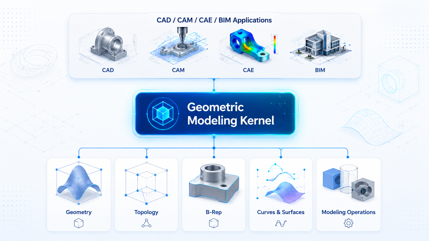
This resource explains how geometric modeling kernels work, how geometry differs from topology, why boundary representation is important, what components make up a CAD kernel and what developers need to understand when integrating geometric modeling functionality into engineering software.
What Is a Geometric Kernel?
In engineering software, a geometric kernel — also commonly referred to as a geometric modeling kernel, CAD kernel, geometry kernel or, in some contexts, a solid modeling kernel — provides the fundamental representation and computation layer for geometric models.
The user of a CAD application may interact with commands such as Extrude, Cut, Fillet or Shell. Behind those commands, the geometric kernel performs much more detailed work.
A kernel may need to:
- construct curves and surfaces;
- calculate intersections;
- create and modify solid bodies;
- maintain topological connectivity;
- trim surfaces;
- rebuild faces and edges;
- validate model consistency;
- work with numerical tolerances;
- calculate geometric properties;
- generate data for visualization and downstream engineering workflows.
A simplified software stack looks like this:
CAD / CAM / CAE / BIM Application
↓
Geometric Modeling Kernel
↓
Geometry + Topology + Modeling Algorithms
↓
Curves · Surfaces · Faces · Edges · Shells · Solid Bodies
What Does a Geometric Modeling Kernel Do?
A geometric modeling kernel typically provides several interconnected groups of functionality.
| Area | Typical functionality |
|---|---|
| Geometry | Points, vectors, lines, arcs, circles, spline curves, planes, cylinders, cones and freeform surfaces |
| Topology | Vertices, edges, loops, faces, shells and bodies |
| Solid Modeling | Creation and modification of B-Rep solids and precise engineering models |
| Modeling Operations | Extrusion, revolution, sweep, loft and Boolean operations |
| Local Operations | Filleting, chamfering, shelling and offsetting |
| Geometric Calculations | Intersections, projections, distances and closest-point calculations |
| Validation | Model consistency, topology and tolerance checking |
| Tessellation | Conversion of precise geometry into polygonal representations |
Geometry and Topology
One of the fundamental concepts in geometric modeling is the distinction between geometry and topology.
Geometry
Geometry describes mathematical shape.
Common geometric entities include:
- points;
- lines;
- circles;
- spline curves;
- planes;
- cylindrical surfaces;
- conical surfaces;
- NURBS and other parametric surfaces.
Topology
Topology describes how geometric entities are bounded and connected inside a model.
Typical topological entities include:
- vertices;
- edges;
- loops;
- faces;
- shells;
- bodies.
For example, a mathematical cylindrical surface can extend indefinitely. A cylindrical face in a CAD model represents only a bounded region of that surface.
The surface defines the mathematical shape, while edges and loops determine which part of the surface belongs to the model.
Geometry answers: What is the mathematical shape?
Topology answers: How is that shape bounded and connected inside the model?
For a more detailed explanation, read Geometric Modeling Kernel Concepts for CAD Developers.
Boundary Representation (B-Rep)
Boundary Representation, usually abbreviated as B-Rep, is one of the most important representations used by geometric modeling kernels.
Instead of describing a solid only as a collection of display triangles, B-Rep represents the exact boundary of an object using mathematical geometry and topology.
A typical B-Rep solid can contain:
Geometry
- curves;
- surfaces;
- points.
Topology
- vertices;
- edges;
- loops;
- faces;
- shells;
- bodies.
A face references a mathematical surface. An edge normally references part of a curve. Loops define face boundaries. Connected faces form shells, while closed shells can represent solid bodies.
This structure allows CAD and engineering applications to perform operations that depend on precise geometry rather than visual approximation.
A polygon mesh primarily represents the shape used for visualization and polygonal processing. A B-Rep model additionally provides the mathematical and topological structure required for precise modeling operations.
Read the complete guide: B-Rep Solid Modeling: Developer Reference and Examples.
How a Geometric Kernel Works
A modeling operation that appears simple in a CAD interface can require many geometric and topological calculations internally.
Consider subtracting a cylinder from a rectangular block.
The application presents this as a single Boolean subtraction command. Internally, the geometric kernel may need to:
- identify potentially intersecting faces;
- calculate surface-to-surface intersections;
- generate intersection curves;
- split existing faces;
- classify the resulting regions;
- remove unnecessary regions;
- construct new edges and loops;
- rebuild the topology of the resulting body;
- validate the final model.
The visible result is simply a block with a cylindrical hole.
Internally, however, its B-Rep structure may have changed substantially.
This is one of the main differences between geometric modeling and 3D rendering. A rendering engine determines how geometry appears on screen. A geometric modeling kernel determines what the model mathematically is and how it can be modified.
Core Geometric Modeling Operations
Engineering applications commonly require a broad range of modeling operations.
Extrusion
Extrusion creates geometry by moving a profile along a specified direction. A closed planar profile can be used to construct a solid body.
Revolution
A profile is rotated around an axis to generate a surface or solid.
Sweep
A profile moves along a trajectory. Sweep operations are commonly used for pipes, rails and other path-based shapes.
Loft
A loft constructs geometry through a sequence of cross-sections.
Boolean Operations
Boolean operations combine or modify solid bodies:
- union;
- subtraction;
- intersection.
Filleting
Fillets replace sharp transitions between faces with rounded blending geometry.
Chamfering
Chamfers create beveled transitions between neighboring regions.
Shelling
Shell operations create thin-walled structures by offsetting selected regions of a solid.
Offsetting
Curves and surfaces can be offset by specified distances to construct related geometry.
Geometric Intersections
Curve-curve, curve-surface and surface-surface intersection algorithms are fundamental building blocks for many higher-level modeling operations.
More information:
- Common Geometric Modeling Operations in CAD Applications
- Solid Modeling Operations for Engineering Software Developers
Geometric Kernel Architecture
A production CAD kernel is not a single algorithm. It is a coordinated software system containing several layers.
A simplified architecture can be represented as:
Application API
↓
Modeling Operations
↓
B-Rep & Topology
↓
Geometric Algorithms
↓
Curves & Surfaces
↓
Mathematical Foundation
Geometric Representation
The representation layer defines mathematical entities such as curves, surfaces, coordinate systems, transformations and vectors.
Topological Representation
The topology layer describes bounded and connected model entities such as faces, edges, shells and bodies.
Geometric Algorithms
This layer contains calculations for intersection, projection, approximation, distance evaluation and other geometric problems.
Modeling Operations
Higher-level algorithms construct and modify engineering objects through Boolean operations, sweeps, lofts, fillets and similar procedures.
Validation and Healing
Real-world CAD models can contain inconsistencies, small gaps and tolerance-related problems. Validation and repair functionality helps identify and resolve these conditions.
Tessellation
Precise geometry usually needs to be converted into triangles before it can be rendered efficiently by a graphics engine.
Application Programming Interface
The API exposes kernel functionality to CAD, CAM, CAE, BIM and other engineering applications.
Read more: CAD Kernel Architecture: Core Components Explained.
Geometric Kernel vs CAD Kernel vs Solid Modeling Kernel
The terminology surrounding geometric modeling software is not completely standardized.
| Term | Typical meaning |
|---|---|
| Geometric kernel | General software component responsible for geometric representation and computation |
| Geometric modeling kernel | Kernel designed to construct and modify geometric models |
| CAD kernel | Common engineering term for a modeling kernel used by CAD software |
| Solid modeling kernel | Kernel focused strongly on constructing and modifying solid bodies |
| Geometry kernel | Shorter term sometimes used for geometric computation technology |
In practice, these terms often overlap.
The exact meaning depends on the architecture and capabilities of the software being discussed.
Where Geometric Kernels Are Used
Geometric modeling kernels are not limited to traditional mechanical CAD.
CAD
Computer-aided design applications use geometric kernels to construct and modify precise 2D and 3D models.
CAM
Manufacturing applications can analyze surfaces, edges and bodies when calculating machining regions and toolpaths.
CAE
Engineering analysis software uses CAD geometry during preprocessing, model preparation and mesh generation.
BIM and AEC
Building and infrastructure applications require geometric representation, intersections, solids and spatial calculations.
Additive Manufacturing
Geometry processing can be required during model preparation, validation and conversion before manufacturing.
Inspection and Metrology
Precise mathematical geometry can be compared with measured or scanned data.
Engineering Automation
Specialized engineering applications can integrate a geometric modeling kernel as an SDK instead of implementing complex geometric algorithms from scratch.
Example of a Production Geometric Modeling Kernel
Developers building engineering applications can either create their own modeling technology or integrate an existing kernel.
One example is C3D Modeler, a geometric modeling kernel designed for developers of CAD, CAM, CAE, BIM and other engineering applications.
It supports multiple approaches to geometric modeling, including:
- solid modeling;
- surface modeling;
- wireframe modeling;
- direct modeling;
- sheet metal modeling.
Its functionality includes Boolean operations, extrusion, revolution, sweeps, fillets, chamfers, curve and surface operations, geometric calculations and B-Rep-based model representation.
For teams developing their own engineering software, using an established geometric kernel can remove the need to implement the complete mathematical and topological modeling layer internally.
Building a CAD Application Around a Geometric Kernel
A geometric kernel normally forms only one part of a complete CAD system.
A production application may also require:
- a user interface;
- a feature or model tree;
- sketching functionality;
- geometric and dimensional constraints;
- visualization;
- file management;
- undo and redo;
- parametric dependencies;
- engineering metadata;
- CAD data exchange;
- application-specific workflows.
The geometric kernel provides the modeling foundation while the application defines higher-level user and engineering functionality.
This separation allows developers to focus on their product while relying on a specialized geometry layer for complex mathematical operations.
Read: Building a 3D CAD Application: Geometry Kernel Integration Guide.
Geometric Modeling Resources for Developers
B-Rep Solid Modeling
Learn how boundary representation combines mathematical geometry with vertices, edges, loops, faces, shells and bodies.
Building a 3D CAD Application
Learn how a geometric kernel fits into the architecture of a 3D CAD application and interacts with higher-level functionality.
Read the 3D CAD Application Guide →
CAD Kernel Architecture
Explore the representation, topology, geometric algorithms, validation, tessellation and API layers of a CAD kernel.
Read CAD Kernel Architecture →
Common Geometric Modeling Operations
Review common modeling operations including extrusion, revolution, Boolean operations, fillets and intersections.
Read Geometric Modeling Operations →
Geometric Modeling Kernel Concepts
A developer-oriented introduction to geometry, topology, B-Rep, numerical tolerances and modeling APIs.
Read Geometric Modeling Kernel Concepts →
Solid Modeling Operations
Learn what happens internally when engineering software performs common solid modeling operations.
Read Solid Modeling Operations →
Frequently Asked Questions
What is a geometric kernel?
A geometric kernel is a software component that provides mathematical representations and algorithms for creating, modifying and analyzing geometric models. It commonly works with curves, surfaces, topology and solid bodies.
What is a geometric modeling kernel?
A geometric modeling kernel is the geometry-processing foundation used by CAD and other engineering applications. It provides data structures and algorithms for constructing precise models and performing modeling operations.
What does a CAD kernel do?
A CAD kernel handles core geometric calculations and modeling operations such as constructing curves and surfaces, building solid bodies, calculating intersections, performing Boolean operations and modifying B-Rep topology.
Is a geometric kernel the same as a rendering engine?
No. A rendering engine primarily determines how geometry is displayed. A geometric kernel represents and modifies the precise mathematical model used by engineering applications.
What is B-Rep in CAD?
B-Rep, or Boundary Representation, describes a solid through its boundary. Faces, edges and vertices define the topological structure, while curves and surfaces provide the underlying mathematical geometry.
What operations can a geometric modeling kernel perform?
Typical operations include extrusion, revolution, sweep, loft, Boolean union, subtraction, intersection, filleting, chamfering, shelling, offsetting and geometric intersection calculations.
Why are numerical tolerances important in geometric modeling?
Computer calculations use finite-precision numbers. Geometric kernels therefore require tolerance rules to determine when calculated points, curves, surfaces and boundaries should be considered coincident or connected.
Do CAD applications need a geometric kernel?
Complex CAD systems require geometric modeling functionality, but developers do not necessarily need to implement it themselves. Applications can integrate an existing geometric modeling kernel or SDK as their geometry-processing layer.
About Geometric Kernel
Geometric Kernel is a technical resource focused on geometric modeling, CAD kernel architecture, B-Rep, solid modeling and engineering software development.
The goal is to provide practical explanations of the concepts, data structures and algorithms encountered when building software that creates and modifies precise 3D geometry.
Topics
Geometric kernel · Geometric modeling kernel · CAD kernel · Geometry kernel · Solid modeling · B-Rep · CAD development · 3D geometry